Parabolic antenna
From Wikipedia, the free encyclopedia

A parabolic antenna is a high-gain reflector antenna used for radio, television and data communications, and also for radiolocation (RADAR), on the UHF and SHF parts of the electromagnetic spectrum. The relatively short wavelength of electromagnetic (radio) energy at these frequencies allows reasonably sized reflectors to exhibit the very desirable highly directional response for both receiving and transmitting.
With the advent of TVRO and DBS satellite television, the parabolic antenna became a ubiquitous feature of urban, suburban, and even rural, landscapes. Extensive terrestrial microwave links, such as those between cellphone base stations, and wireless WAN/LAN applications have also proliferated this antenna type. Earlier applications included ground-based and airborne radar and radio astronomy. The largest "dish" antenna in the world is the Arecibo Observatory's radio telescope at Arecibo, Puerto Rico, but, for beam-steering reasons, it is actually a spherical, rather than parabolic, reflector.
Contents |
[edit] Design

A typical parabolic antenna consists of a parabolic reflector illuminated by a small feed antenna.
The reflector is a metallic surface formed into a paraboloid of revolution and (usually) truncated in a circular rim that forms the diameter of the antenna. This paraboloid possesses a distinct focal point by virtue of having the reflective property of parabolas in that a point light source at this focus produces a parallel light beam aligned with the axis of revolution.
The feed antenna is placed at the reflector focus. This antenna is typically a low-gain type such as a half-wave dipole or a small waveguide horn. In more complex designs, such as the Cassegrain antenna, a sub-reflector is used to direct the energy into the parabolic reflector from a feed antenna located away from the primary focal point. The feed antenna is connected to the associated radio-frequency (RF) transmitting or receiving equipment by means of a coaxial cable transmission line or hollow waveguide.
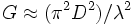
Considering the parabolic antenna as a circular aperture gives the following approximation for the maximum gain:
or
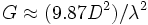
where:
 is power gain over isotropic
 is reflector diameter in same units as wavelength
 is wavelength
Practical considerations of antenna effective area and sidelobe suppression reduce the actual gain obtained to between 35 and 55 percent of this theoretical value. For theoretical considerations of mutual interference (at frequencies between 2 and c. 30 GHz - typically in the Fixed Satellite Service) where specific antenna performance has not been defined, a reference antenna based on Recommendation ITU-R S.465 is used to calculate the interference, which will include the likely sidelobes for off-axis effects.
Applying the formula to the 25-meter-diameter antennas used by the VLA and VLBA radio telescopes at a wavelength of 21 cm (1.42 GHz, a common radio astronomy frequency) yields an approximate maximum gain of 140,000 times or about 50 dBi (decibels above the isotropic level).
[edit] Structure

The reflector dish can be solid, mesh or wire in construction and it can be either fully circular or somewhat rectangular depending on the radiation pattern of the feeding element. Solid antennas have more ideal characteristics but are troublesome because of weight and high wind load. Mesh and wire types weigh less, are easier to construct and have nearly ideal characteristics if the holes or gaps are kept under 1/10 of the wavelength.
More exotic types include the off-set parabolic antenna, Gregorian and Cassegrain types. In the off-set, the feed element is still located at the focal point, which because of the angles utilized, is usually located below the reflector so that the feed element and support do not interfere with the main beam. This also allows for easier maintenance of the feed, but is usually only found in smaller antennas.
The Gregorian and Cassegrain types, sometimes generically referred to as "dual optics" antennas, utilize a secondary reflector, or "sub-reflector", allowing for better control over the colimated beam as well as allowing the antenna feed system to be more compact. These antennas are usually much larger where prime focus and off-set construction are not as practical. The feed element is usually located in a "feed horn" which protrudes out from the main reflector. This setup is used when the feed element is bulky or heavy such as when it contains a pre-amplifier or even the actual receiver or transmitter. Parabolic antenna theory closely follows optics theory. So a Gregorian antenna can be identified by the fact that it uses a concave sub-reflector, while a Cassegrain antenna uses a convex sub-reflector.
[edit] See also
- Radio telescope
- Satellite dish
- Simulsat (a quasi parabolic antenna which is spherical in one plane and parabolic in another)
- Corner reflector
[edit] External links
- Antenna types: Parabolic Dish Antenna from Educypedia
- Online pointing utility using google maps, and each satellite channel list: http://www.dishpointer.com/

